Introduction
With a personal goal of developing a deep understanding of quadcopter dynamics, I built my own quadcopter based on the open-source Carbon Aeronautics drone. This required purchasing parts online, making modifications, and assembling the whole quadcopter from the ground up until flight testing. Even though it may sound like a straightforward path from assembly to testing, I spent months stuck trying to make it fly due to both hardware and software issues. Little by little, the fun turned into frustration.
One of the main issues I faced was that my quadcopter flipped on every takeoff. After extensive troubleshooting, I became convinced that the problem was the motor mixer algorithm, without realizing there were other possible causes for this behavior. Weeks later, I discovered that the real issue was the electronic speed controller (ESC) miscalibration. However, by then I had already spent a lot of time learning about motor mixer algorithms, to the point that I derived one for my quadcopter to confirm whether it was actually correct.
What you will learn
The purpose of this post is to share the derivation of the motor mixer from the quadcopter dynamic, assuming you already know some basic physics and linear algebra. This gives us a starting idea of how popular flight controllers handle motor mixers and it helps us understand that the PID controller implicitly compensates for the drone’s physical parameters, so that in practice we mainly focus on tuning the drone experimentally.
A Note to the Reader
The content presented here is intended primarily for hobbyist purposes and is based on my personal notes. My goal is to simplify complex concepts as much as possible for my quadcopter project, so some details may be oversimplified or contain mistakes.
Quadcopter
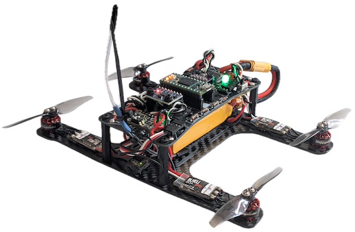
The open-source quadcopter is a low-cost micro H-configuration drone powered by a 2S LiPo battery and designed for teaching mechanical, electronic, and flight controller software concepts. Its greatest advantage is its well-documented manual and YouTube videos, which cover everything from assembly and flight testing to the quadcopter dynamics simulation. I highly recommend it if you are interested in building your own drone from scratch.
This platform was especially helpful for my learning goals because both the hardware and software are fully hackable and adaptable. This allowed me to modify the design and develop my own flight controller version. Some of the changes I made include a custom carbon-fiber lower frame, an sBUS receiver, different motors and ESCs, flight logging through an SD card, and several software features such as a task scheduler, arming-disarming functionality, and buzzer notifications. The source code is available on GitHub.
The video below shows the quadcopter flying in acro mode.
Motor Mixer Algorithm

Fig. 1. General motor mixer algorithm diagram.
As shown in Fig. 1, the motor mixer algorithm combines the outputs of the controller to generate individual motor commands. In general, the PID controller produces the desired thrust and the desired roll, pitch, and yaw torques. The mixer then converts these values into individual motor thrust commands according to the quadcopter geometry.
Normally, the desired motor thrust commands from the mixer need to be converted into motor control signals (PWM, UAVCAN, etc.) using a thrust scaling curve. For this hobby quadcopter, however, the PID controller is tuned specifically to output PWM-equivalent commands, so the mixer directly produces PWM motor commands that are fed to the ESCs, as demonstrated in Fig. 2.

Fig. 2. Motor mixer algorithm outputs PWM motor commands for this quadcopter.
Therefore, the purpose of the mixer algorithm is to determine the contribution of each motor required to achieve the desired motion of the quadcopter.
Find Motor Mixer Algorithm iteratively
The terms input and command are used interchangeably (e.g., throttle input = throttle command)
The manual of the Carbon Aeronautics drone explains in detail that the motor mixer for this drone is a linear combination of the throttle, roll, pitch, and yaw inputs, as given by equation (1). To find the correct combination, we have to use the quadcopter configuration and analyze each motion scenario until the mixer algorithm is correct. This is a very tedious iterative approach, but it allows us to avoid going through the quadcopter dynamics mathematically. Note that these inputs, also referred to as commands, are provided directly by the controller, as indicated in Fig. 2.
Rewriting the mixer in a clean matrix form, we have
For now, let’s assume the motor mixer is simply the sum of all inputs without considering their signs. We will add the appropriate signs as we examine each case.
Let’s consider the rolling case, where we want the quadcopter to roll to the right, see Fig. 3. First, we assume that an input percentage maps directly to a motor power percentage. Suppose the quadcopter is hovering with a throttle input of 50%, which causes each motor to operate at 50% of its power. We then apply a roll input of 20%, while assuming there is no pitch input (0%) and no yaw input (0%) interfering with the roll movement. Therefore, the above placeholder mixer consists only of the throttle and roll inputs.
From Fig. 3, we see that to roll to the right, we have to decrease the power of motors 1 and 2 by 20%. At the same time, we have to increase the power of motors 3 and 4 by 20%. This means we subtract the roll input from the throttle input for motors 1 and 2, and add it to the throttle input for motors 3 and 4. This leads to the following mixer for rolling to the right. If we plug in the value of the roll input, we can clearly see that the two right motors provide less power, while the two left motors provide more power to achieve the rightward movement.

Fig. 3. (a) The quadcopter rolling to the right. (b) A 2D representation of the roll motion. $^{1}$
The next question is whether this mixer also works for rolling to the left, where motors 1 and 2 need higher power and motors 3 and 4 need lower power, as shown in Fig. 4. Clearly, this mixer still produces a roll to the right if we provide a positive roll input. Therefore, we must provide a negative roll input so that the signs in the mixer are effectively reversed, resulting in a roll to the left. If we plug in the negative value of the roll input, we can clearly see that the drone rolls to the left. With this in mind, the sign of the roll input determines the direction of the roll motion.

Fig. 4. (a) The quadcopter rolling to the left. (b) A 2D representation of the roll motion.$^{1}$
To obtain the mixers for pitch and yaw motions, we follow the same iterative approach. This is how we arrive at the final motor mixer algorithm in equation (1) for this quadcopter.
Find Motor Mixer Algorithm mathematically
From studying the quadcopter rigid-body dynamics, we learned that the translational dynamics of the vehicle depend on the total thrust, $T_{total}$, and the rotational dynamics depend on the three body torques, $\tau_{roll}$, $\tau_{pitch}$, and $\tau_{yaw}$.
By collecting the equations that describe these dynamics, we can form a matrix relationship between the four motor thrusts and the total thrust and three body torques. This relationship is represented by the matrix $M$:
$$ \begin{bmatrix} T_{total} \\ \tau_{roll} \\ \tau_{pitch} \\ \tau_{yaw} \end{bmatrix} = M \begin{bmatrix} T_1 \\ T_2 \\ T_3 \\ T_4 \end{bmatrix} \tag{7} $$By inverting $M$, we obtain the motor mixer matrix, $M^{-1}$, which computes the individual motor thrusts required to produce the desired total thrust and body torques.
$$ \begin{bmatrix} T_1 \\ T_2 \\ T_3 \\ T_4 \end{bmatrix} = M^{-1} \begin{bmatrix} T_{total} \\ \tau_{roll} \\ \tau_{pitch} \\ \tau_{yaw} \end{bmatrix} \tag{8} $$I personally prefer this motor mixer derivation approach because it allows us to verify that the resulting mixer is physically consistent and can be extended to other multirotor configurations.
Total Thrust

Fig. 5. Thrust force generated by each rotor.$^{1}$
It is defined that the thrust force, $T_i$, generated by a propeller is directly proportional to the square of the rotor angular velocity, $\omega$, with thrust coefficient $k_T$:
$$ \begin{aligned} T_i &= k_T \omega_i^2 \qquad i=1,2,3,4\tag{9} \end{aligned} $$Therefore, the total vertical thrust is the sum of the thrust generated by each rotor:
$$ T_{total} = T_1+T_2+T_3+T_4\tag{10} $$Aerodynamic Drag Torque
It is also known that a propeller generates an aerodynamic drag torque, $Q_i$, that is proportional to the square of the rotor angular velocity, $\omega$, with moment coefficient $k_Q$. This aerodynamic drag torque acting on the propeller is opposite to the rotation of the propeller. The sign of the drag torque can be determined from the propeller spin direction and the body-frame coordinate convention.
$$ Q_{i} = k_{Q}\omega_{i}^{2}\qquad i=1,2,3,4\tag{11} $$
Fig. 6. Proper sign of the aerodynamic drag torque using the right-hand rule.
To obtain the drag torque with its proper sign for this quadcopter, we use the marked axes of the IMU board as the body-frame coordinate convention, where $+x$ is forward and $+y$ is left, as shown in Fig. 6. By taking the cross product of these axes, the $+z$ axis points upward:
$$ +\vec{z} = +\vec{x} \times +\vec{y} \tag{12} $$Applying the right-hand rule to the $+z$ axis, a counterclockwise (CCW) propeller has a positive angular velocity, $+ω$, about $+z$. Since aerodynamic drag opposes the rotation, a counterclockwise (CCW) propeller generates a negative aerodynamic drag torque, whereas a clockwise (CW) propeller produces a positive aerodynamic drag torque.
Roll and Pitch Torque
The roll and pitch torques result from differences in the thrust produced by opposing rotors acting at a distance from the center of the quadcopter. We derive these torques from the standard definition of torque, which is the cross product of the lever-arm vector and the force vector.
$$ \vec{\tau} = \vec{r} \times \vec{F} \tag{13} $$Hence, the net torque acting on the drone body is the sum of all individual torques.
$$ \vec{\tau}_{net} = \sum \vec{r_i} \times \vec{F_i} \tag{14} $$Once we perform the cross product and separate the x-axis and y-axis components, the roll torque and pitch torque are defined as
$$\tau_\text{roll} = \sum y_iT_i \tag{15}$$$$\tau_\text{pitch} = \sum(-x_iT_i) \tag{16}$$Fig. 7 illustrates the correct coordinate position of each motor of this quadcopter, where the axes of the IMU board are used as the body-frame coordinate convention. In this convention, $+x$ is forward, $+y$ is left, and $+z$ is upward.

Fig. 7. Motor $(x,y)$ position using the body-frame coordinate convention.$^{1}$
By plugging in the corresponding y-coordinates of each motor position, we obtain the final roll torque.
$$ \begin{aligned} \tau_\text{roll} = \sum y_iT_i = y_1T_1+y_2T_2+y_3T_3+y_4T_4 \\ \tau_\text{roll} = (-L_y)T_1+(-L_y)T_2+(L_y)T_3+(L_y)T_4 \\ \tau_\text{roll} = L_y(-T_1-T_2+T_3+T_4) \tag{17} \end{aligned} $$Similarly, by plugging in the corresponding x-coordinates of each motor position, we obtain the final pitch torque.
$$ \begin{aligned} \tau_\text{pitch} = \sum(-x_iT_i) = -(x_1T_1+x_2T_2+x_3T_3+x_4T_4) \\ \tau_\text{pitch} = -[(L_x)T_1+(-L_x)T_2+(-L_x)T_3+(L_x)T_4] \\ \tau_\text{pitch} = L_x(-T_1+T_2+T_3-T_4) \tag{18} \end{aligned} $$Yaw Torque
The aerodynamic drag torque, $Q_i$, acting on each propeller generates an equal-magnitude reaction torque on the drone frame through the motor–propeller interaction. This reaction torque is responsible for the yaw motion of the quadcopter. Hence, the net yaw torque acting on the quadcopter frame is the sum of the reaction torques from all rotors about the body-frame z-axis.
$$ \tau_{yaw} = \sum_{i=1}^{4} s_i Q_i \qquad s_i \in \{+1, -1\} \tag{19} $$For this quadcopter, a positive yaw torque corresponds to a counterclockwise rotation about the body-frame z-axis according to the right-hand rule, see Fig. 8. A counterclockwise (CCW) rotor generates a reaction torque on the frame in the clockwise direction, which corresponds to a negative yaw torque contribution. Conversely, a clockwise (CW) rotor generates a positive yaw torque contribution. Therefore, the sign factor $s_i$ is defined as
$$ s_i = \begin{cases} +1 & \text{CW rotor} \\ -1 & \text{CCW rotor} \end{cases} \tag{20} $$
Fig. 8. For each rotor, the sign factor indicates the positive or negative yaw torque contribution about the body-frame z-axis according to its spinning direction and the right-hand rule.$^{1}$
Fig. 8 shows the sign factor, $s_i$, associated with each rotor’s spin direction. Substituting these values in (19) yields
$$ \tau_{yaw} = - Q_1 + Q_2-Q_3 + Q_4 \tag{21} $$By introducing the rotor drag-to-thrust coefficient ratio $\gamma = \frac{k_Q}{k_T}$, it is convenient to express $Q_i$ in terms of the thrust force $T_i$.
$$ Q_i = \frac{k_Q}{k_T} T_i = \gamma T_i \qquad i=1,2,3,4\tag{22} $$Substituting into (21), we obtain the final yaw torque in terms of $T_i$ and $\gamma$.
$$ \tau_{yaw} = -\gamma T_1+\gamma T_2- \gamma T_3+\gamma T_4 \\ \tau_{yaw} = \gamma (-T_1+T_2-T_3+T_4) \tag{23} $$Defining Motor Mixer Matrix
Grouping the total thrust, roll torque, pitch torque, and yaw torque in the following order, we have:
$$ \begin{aligned} T_\text{total} = T_1+T_2+T_3+T_4 \\ \tau_\text{roll} = L_y(-T_1-T_2+T_3+T_4) \\ \tau_\text{pitch} = L_x(-T_1+T_2+T_3-T_4) \\ \tau_\text{yaw} = \gamma (-T_1+T_2-T_3+T_4) \tag{24} \end{aligned} $$Representing these equations in matrix form, we get
$$ \begin{bmatrix} T_{total} \\ \tau_{roll} \\ \tau_{pitch} \\ \tau_{yaw} \end{bmatrix} = \begin{bmatrix} 1 & 1 & 1 & 1 \\ -L_y & -L_y & L_y & L_y \\ -L_x & L_x & L_x & -L_x \\ -\gamma & \gamma & -\gamma & \gamma \end{bmatrix} \begin{bmatrix} T_1 \\ T_2 \\ T_3 \\ T_4 \tag{25} \end{bmatrix} $$To obtain the individual thrust generated by each rotor, we invert the matrix
$$ \begin{bmatrix} T_{1} \\ T_{2} \\ T_{3} \\ T_{4} \end{bmatrix} = \begin{bmatrix} \frac14 & -\frac{1}{4L_y} & -\frac{1}{4L_x} & -\frac{1}{4\gamma} \\ \frac14 & -\frac{1}{4L_y} & \frac{1}{4L_x} & \frac{1}{4\gamma} \\ \frac14 & \frac{1}{4L_y} & \frac{1}{4L_x} & -\frac{1}{4\gamma} \\ \frac14 & \frac{1}{4L_y} & -\frac{1}{4L_x} & \frac{1}{4\gamma} \end{bmatrix} \begin{bmatrix} T_{total} \\ \tau_{roll} \\ \tau_{pitch} \\ \tau_{yaw} \tag{26} \end{bmatrix} $$We can go one step further by normalizing the matrix. This is done by factoring the physical constants into the input vector and leaving the matrix entries bounded between -1 and +1.
$$ \begin{bmatrix} T_{1} \\ T_{2} \\ T_{3} \\ T_{4} \end{bmatrix} = \begin{bmatrix} 1 & -1 & -1 & -1 \\ 1 & -1 & 1 & 1 \\ 1 & 1 & 1 & -1 \\ 1 & 1 & -1 & 1 \end{bmatrix} \begin{bmatrix} \frac14T_{total} \\ \frac{1}{4L_{y}}\tau_{roll} \\ \frac{1}{4L_{x}}\tau_{pitch} \\ \frac{1}{4\gamma}\tau_{yaw} \tag{27} \end{bmatrix} $$In the PID controller design, the controller produces desired $T_{total}$, $\tau_{roll}$, $\tau_{pitch}$, and $\tau_{yaw}$. We represent these quantities by the inputs $u_1$, $u_2$, $u_3$, and $u_4$, respectively. Hence, the motor mixer matrix becomes
$$ \begin{bmatrix} T_{1} \\ T_{2} \\ T_{3} \\ T_{4} \end{bmatrix} = \begin{bmatrix} 1 & -1 & -1 & -1 \\ 1 & -1 & 1 & 1 \\ 1 & 1 & 1 & -1 \\ 1 & 1 & -1 & 1 \end{bmatrix} \begin{bmatrix} \frac{1}{4}u_1 \\ \frac{1}{4L_{y}}u_2 \\ \frac{1}{4L_{x}}u_3 \\ \frac{1}{4\gamma}u_4 \end{bmatrix} \tag{28} $$Finally, by defining $\tilde{u}_1$, $\tilde{u}_2$, $\tilde{u}_3$, $\tilde{u}_4$, we can rewrite the mixer matrix as
$$ \begin{bmatrix} T_{1} \\ T_{2} \\ T_{3} \\ T_{4} \end{bmatrix} = \begin{bmatrix} 1 & -1 & -1 & -1 \\ 1 & -1 & 1 & 1 \\ 1 & 1 & 1 & -1 \\ 1 & 1 & -1 & 1 \end{bmatrix} \begin{bmatrix} \tilde{u}_1 \\ \tilde{u}_2 \\ \tilde{u}_3 \\ \tilde{u}_4 \tag{29} \end{bmatrix} $$where
$$ \tilde{u}_1 = \frac{1}{4}u_1, \qquad \tilde{u}_2 = \frac{1}{4L_{y}}u_2, \qquad \tilde{u}_3 = \frac{1}{4L_{x}}u_3, \qquad \tilde{u}_4 = \frac{1}{4\gamma}u_4 $$At this point, we can see that the motor mixer matrix in (29) from the dynamic model is identical to the motor mixer in (2) from the iterative approach. Therefore, the dynamic derivation verifies that the iterative motor mixer is correct.
$$ \begin{bmatrix} \text{output motor 1} \\ \text{output motor 2} \\ \text{output motor 3} \\ \text{output motor 4} \end{bmatrix} = \begin{bmatrix} 1 & -1 & -1 & -1 \\ 1 & -1 & 1 & 1 \\ 1 & 1 & 1 & -1 \\ 1 & 1 & -1 & 1 \end{bmatrix} \begin{bmatrix} \text{throttle command} \\ \text{roll command} \\ \text{pitch command} \\ \text{yaw command} \end{bmatrix} $$Physical Parameters and PID tuning
We observe that the final motor mixer equation (29) depends on the parameters $\frac{1}{4}$, $L_x$, $L_y$ and $\gamma$. In practice, we can measure these parameters experimentally, but for this hobby quadcopter there is no need to do so because the controller gains are tuned to compensate for their effect. Once this is done, the PID outputs can be interpreted as PWM-equivalent motor command corrections rather than thrust and torque commands. Consequently, the final motor mixer combines these corrections to generate PWM motor commands for the ESCs.
To see how the physical parameters are incorporated into the PID gains, let’s consider the roll torque input $u_2$, defined as a continuous-time PID controller
$$ u_2 =\tau_{roll} = K_P e_{roll} + K_I \int e_{roll}\,dt + K_D \frac{de_{roll}}{dt} \tag{30} $$We know $\tilde{u}_2$ and by substituting $u_2$, we get
$$ \tilde{u}_2 = \frac{1}{4L_{y}}u_2 = \frac{1}{4L_{y}} \left( K_{P}e_{roll} + K_{I}\int e_{roll}\,dt + K_{D}\frac{d e_{roll}}{dt} \right) \tag{31} $$Next, we define the following scaled PID gains that incorporate the physical constant $\frac{1}{4L_y}$
$$ \tilde{K}_{P} = \frac{1}{4L_{y}}K_{P}, \qquad \tilde{K}_{I} = \frac{1}{4L_{y}}K_{I}, \qquad \tilde{K}_{D} = \frac{1}{4L_{y}}K_{D} $$Then $\tilde{u}_2$ remains a PID controller with scaled gains, producing a command. Therefore, all we have to do is tune these gains.
$$ \tilde{u}_2 = \tilde{K}_{P}e_{roll} + \tilde{K}_{I}\int e_{roll}\,dt + \tilde{K}_{D}\frac{d e_{roll}}{dt} \tag{32} $$From this example, we see that the physical parameters can be omitted from the motor mixer because their effect is implicitly captured by the PID gains. As a result, the PID outputs are interpreted as motor command corrections rather than explicit thrust and torque commands. The main drawback of this approach is that the PID gains must be retuned whenever the propellers, motors, or drone size change.
Code Implementation
For my version of the flight controller, I implemented the motor mixer directly in its matrix form. I find this approach much easier to understand because it closely matches the mathematical derivation and helps me become more familiar with quadcopter terminology. The following C++ snippet completely summarizes the mixer, and it still amazes me that this implementation actually works and is able to fly a real quadcopter.
    // Motors.h
    #define NUM_MOTORS 4
    float _command_inputs[4] = {0.0f};
    float _mixed_motor_outputs[NUM_MOTORS] = {0.0f};
    float _mixer[NUM_MOTORS][NUM_MOTORS] = {
        {1, -1, -1, -1}, // Motor 1
        {1, -1, 1, 1},   // Motor 2
        {1, 1, 1, -1},   // Motor 3
        {1, 1, -1, 1},   // Motor 4
    };
    // Motors.cpp
    void Motors::set_command_inputs(float throttle_command, float roll_command, float pitch_command, float yaw_command)
    {
        _command_inputs[Input::THROTTLE] = throttle_command;
        _command_inputs[Input::ROLL] = roll_command;
        _command_inputs[Input::PITCH] = pitch_command;
        _command_inputs[Input::YAW] = yaw_command;

        if (_command_inputs[Input::THROTTLE] > SAFE_MAX_THROTTLE)
        {
            _command_inputs[Input::THROTTLE] = SAFE_MAX_THROTTLE;
        }
    }

    void Motors::compute_mixer_outputs()
    {
        for (int i = 0; i < NUM_MOTORS; i++)
        {
            float sum = 0.0f;
            for (int j = 0; j < NUM_MOTORS; j++)
            {
                sum += _mixer[i][j] * _command_inputs[j];
            }
            _mixed_motor_outputs[i] = sum;
        }
    }
Note
- The drone image is adapted from the Carbon Aeronautics manual with annotations and labels added for clarity.
References
- Carbon Aeronautics, “Manual-Quadcopter-Drone.” https://github.com/CarbonAeronautics/Manual-Quadcopter-Drone
- A. Gibiansky, “Quadcopter Dynamics and Simulation.” https://andrew.gibiansky.com/blog/physics/quadcopter-dynamics/
- Cookierobotics.com, “Motor Mixer Theory.” https://cookierobotics.com/066/
- Ardupilot, “Identification of a Multicopter.” https://ardupilot.org/copter/docs/systemid-model-development.html
- PX4 Autopilot, “Multicopter PID Tuning Guide.” https://docs.px4.io/main/en/config_mc/pid_tuning_guide_multicopter
- S. Bouabdallah, “Design and control of quadrotors with application to autonomous flying,” Ph.D. dissertation, EPFL, 2006.
- S. Bouabdallah and R. Siegwart, “Full Control of a Quadcopter,” 2007.
- A. S. Sanca, et al, “Dynamic Modelling of a Quadrotor Aerial Vehicle with Nonlinear Inputs,” 2008.