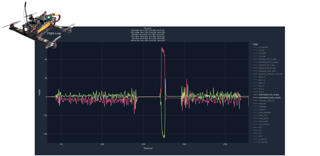
Introduction
The Teensy 4.0 microcontroller is a low-cost, high-performance, and compact board. Carbon Aeronautics took advantage of these capabilities and adapted both its open-source code and PCB frame to use the Teensy 4.0 as the flight controller for a quadcopter. The board provides high processing power through its 600 MHz processor, along with the necessary peripherals and pins to connect the onboard sensors and devices (e.g., IMU, barometer, and ESCs). The flight controller can control the quadcopter at a loop rate of 250 Hz, demonstrating how capable this small board can be.

For my own flight controller version, I extended the capabilities of the board by adding a flight data logger with a microSD card. This involved soldering a microSD card connector to the board, writing the code to store the flight data on the card, and developing a browser-based log viewer in Python. Having a flight logger is a powerful tool because it provides a detailed view of the overall performance of the drone. The recorded data can then be analyzed with a log viewer to diagnose and resolve critical issues. One example is vibration analysis, where we can create a vibration profile from flight data by plotting the raw accelerometer readings.
Implementing a data logger is also challenging because it involves several hardware and software concepts that need to be considered, such as the SD card interface, ring buffer, log formatting and data writing. To simplify SD card logging and achieve fast data transfer, I chose the 4-bit SDIO interface supported by the Teensy 4.0 and the SdFat library by Bill Greiman. For instance, my test showed that the logger can write 512 bytes of data in about 5 microseconds, allowing data to be recorded with minimal impact on the flight loop.
In this post, I am sharing the final result of my first flight logger and what I learned throughout the implementation. You can quickly learn the basic concepts behind a flight logger, giving you an idea of how more complex logging systems work in popular flight controllers (e.g., ArduPilot and Betaflight). If you are curious about the final implementation, you can also check the source code: FlightLogger.h and FlightLogger.cpp.
SDIO Interface
SD: Secure Digital
SDIO: Secure Digital Input Output
One sector = 512 bytes

Fig. 1. Teensy 4.0 capturing and storing flight data on a microSD card.
Fig. 1 presents a general overview of how the Teensy board communicates with the connected devices, processes the acquired data, and stores the resulting data on the microSD card at a loop rate of 250 Hz.
The Teensy 4.0 supports both SPI and the native SD interface, commonly referred to as SDIO, for communicating with an SD card. Unlike 1-bit SPI, SDIO is specifically designed to provide higher data-transfer rates through its 4-bit-wide bidirectional data lines, DAT0–DAT3. This is possible because the chip integrated into the Teensy 4.0, the NXP i.MX RT1062, includes a dedicated Ultra Secured Digital Host Controller (uSDHC) module. The uSDHC handles the SD protocol and serves as the interface between the processor (host) and the SD card, as shown in Fig. 2.

Fig. 2. uSDHC provides the interface between the processor (host) and the SD card.
At the software level, the SdFat library handles SD card operations such as creating files, writing data, managing sectors, and communicating with the SD card. As a result, the flight logger code can focus on collecting and storing flight data without having to deal with the low-level SD communication.
microSD card socket

Fig. 3. (a) Accessible SDIO surface-mount pads on Teensy 4.0. (b) microSD socket 609-5773-1-ND. (c) microSD socket WM14405CT-ND.
The Teensy 4.0 does not have a built-in microSD card socket, but the SDIO surface-mount pads on the bottom of the board are left accessible for mounting a flat-flex cable connector (Fig. 3a). While looking for alternatives on the PJRC forum, I learned that it was also possible to solder a microSD connector directly to these pads. However, I had to deal with the pin-pitch mismatch between the 1.0 mm pitch on the board and the typical 1.1 mm pitch of a microSD socket. Since I wanted a permanently mounted socket with a removable card, I decided to purchase two different push-pull microSD card connectors from DigiKey: 609-5773-1-ND (Fig. 3b) and WM14405CT-ND (Fig. 3c).
After some testing, I found that the 609-5773-1-ND socket is difficult to solder because of its tiny pins and housing shape. The WM14405CT-ND, on the other hand, offers better clearance for soldering to the board. To install this socket, I first insulated the exposed pads next to the SDIO pads with electrical tape to prevent short circuits (Fig. 4a). Considering the pin-pitch mismatch, I carefully aligned the socket pins with the pads and temporarily secured it with hot glue (Fig. 4b). I then soldered the pins to the pads using a small-tip soldering iron and flux. Finally, I cleaned the area, checked continuity with a multimeter, and inspected the solder joints (Fig. 4c).

Fig. 4. (a) Protecting exposed pads with electrical tape. (b) Holding the socket with hot glue. (c) Socket soldered to the SDIO pads. (d) microSD card inserted into the socket.
Log Format

Fig. 5. Log format from the packed C++ structure to memory layout and byte representation.
For my flight data logger, each flight log is stored as a binary .bin file on the microSD card. The file has two types of records: a parameters record and a flight record. The parameters record is written once at the beginning of the file, while the flight record is written at 250 Hz. In the C++ code, both ParametersLog and FlightLog are packed structs whose memory layouts follow the order in which their fields are declared (Fig. 5). This makes it easy to get a pointer to each struct and write its contents directly to the file.
In general, each flight record has a simple format consisting of a header and a payload (Fig. 5). Looking at the code snippet for the parameters and flight structs, each record starts with three header fields: sync, type, and session_id, followed by a payload. The sync field is a unique two-byte value that indicates the beginning of a record, while type specifies whether the payload contains parameters or flight data. The session_id tracks the boot session, with its value incremented and stored in EEPROM each time the Teensy boots. Additionally, each struct is marked with the __attribute__((packed)) directive to reduce its size by removing any padding bytes added by the compiler. For example, the sizeof() operator shows that the size of FlightLog decreases from 136 to 132 bytes when packed is applied.
    #define LOG_SYNC 0xA55A
    #define LOG_TYPE_PARAMETERS 1
    #define LOG_TYPE_FlIGHT 2
    #define DEFAULT_SESSION_ID 0xFFFFFFFF

    struct __attribute__((packed)) ParametersLog
    {
        uint16_t sync = LOG_SYNC;
        uint8_t type = LOG_TYPE_PARAMETERS;
        uint32_t session_id = DEFAULT_SESSION_ID;
        float roll_angle_kp = 0.0f;
        // ...
        float vertical_velocity_kd = 0.0f;
    }

    struct __attribute__((packed)) FlightLog
    {
        uint16_t sync = LOG_SYNC;
        uint8_t type = LOG_TYPE_ENTRY;
        uint32_t session_id = DEFAULT_SESSION_ID;
        uint32_t time_us = 0;
        //...
        uint8_t is_batt_failsafe = 0;
    }
It is worth mentioning that a robust log format often comes with a memory cost. During a few of my flight recording tests, I discovered that the timestamps of some records were out of sequence, with a record occasionally having an earlier timestamp than the one before it. Since the issue occurred randomly, I added the session_id field, enabling the parser to filter out data that does not belong to the current session. The tradeoff is an additional 4 bytes in each struct at every loop iteration, with the benefit of distinguishing records from different sessions. Cases like this demonstrate why popular flight controllers, such as ArduPilot and Betaflight, rely on more advanced log formats for greater robustness.
SD Card Setup
For this project, I used a 16 GB microSD card formatted as FAT32. For now, I manually remove the card from the drone and transfer the log files to my computer, where I process them with the log viewer.
The SdFat library provides the functions needed to initialize the SD card and prepare the log file. These functions return a Boolean value indicating whether the operation was successful. I call them from the init() function of the Logger class, which runs once during program setup.
    void setup()
    {
        //...
        _logger.init(_storage.get_session_id());
        //...
    }
The first step is calling sd.begin() with SdioConfig(FIFO_SDIO) to initialize the SD card and file system for SDIO mode. A successful return indicates that both were configured properly.
    void Logger::init(uint32_t session_id)
    {
        // ...
        if (!sd.begin(SdioConfig(FIFO_SDIO)))
        {
            return;
        }
    }
The next step is creating a unique name for the binary log file with the format flight_log_%03u.bin (e.g., flight_log_001.bin). Starting with an index of 1, the code checks whether the filename already exists with sd.exists(). If it does, the index is incremented until a filename is available.
    void Logger::init(uint32_t session_id)
    {
        // ...
        // Create a file name of the format flight_log_001.bin
        char filename[MAX_FILENAME];
        uint8_t index = 1;
        for (; index < 255; index++)
        {
            snprintf(filename, sizeof(filename), "flight_log_%03u.bin", index);
            if (!sd.exists(filename))
            {
                break;
            }
        }

        if (index == 255)
        {
            return;
        }
    }
With a unique filename, the open() function of the FsFile creates the binary log file on the SD card. The passed flags, O_WRITE | O_CREAT | O_TRUNC, open or create the file for writing and truncate it if it already exists.
    FsFile logFsFile;

    // ...

    void Logger::init(uint32_t session_id)
    {
        // ...
        bool is_file_opened = logFsFile.open(filename, O_WRITE | O_CREAT | O_TRUNC);
        if (!is_file_opened)
        {
            return;
        }
    }
For high rate logging, space for the file should be pre-allocated before flight. Allocating additional space introduces significant delays while the file system searches for free storage (free clusters). During flight testing, I witnessed the search block the main flight loop, destabilizing the drone for a short period and nearly causing a crash.
To prevent this latency, the preAllocate() function of FsFile reserves the required space for the file. I estimated the file size to be 19.8 MB for a 10-minute flight, logging a 132-byte record at 250 Hz:
    // Size to log 132 byte lines at 250Hz for ten minutes.
    #define LOG_FILE_SIZE 132 * 250 * 600 // 19.8 megabytes.

    //...
    void Logger::init(uint32_t session_id)
    {
        // ...
        bool is_file_preallocated = logFile.preAllocate(LOG_FILE_SIZE);
        if (!is_file_preallocated)
        {
            logFile.close();
            return;
        }
    }
Flight records also accumulate faster than they can be written to the SD card at each loop iteration, which results in lost records. To maintain continuous logging, the ring buffer temporarily stores the records until they are written (Fig. 6).

Fig. 6. Ring buffer temporarily holding flight data as 512-byte sectors are written to the microSD card.
In the code, ringBuffer.begin() connects the ring buffer to logFsFile, so the buffered records are saved to the file. For this logger, the ring buffer has a capacity of 3,072 bytes, or 6 × 512 bytes. I selected this capacity experimentally by starting with a multiple of 512 bytes and increasing it until no records were lost when the buffer became full.
    #define SECTOR_SIZE 512

    #define RING_BUF_CAPACITY 6 * SECTOR_SIZE // 3, 072  bytes
    RingBuf<FsFile, RING_BUF_CAPACITY> ringBuffer;

    // ...
    void Logger::init(uint32_t session_id)
    {
        // ...
        ringBuffer.begin(&logFsFile);
    }
Finally, I keep a global is_sd_card_ready variable to track whether the SD card setup completed successfully. This prevents the logger from attempting to write flight data when one of the setup steps fails.
    void Logger::init(uint32_t session_id)
    {
        // ...
        is_sd_card_ready = false;
        // SD card initialization ...
        // Create file name ...
        // File initialization ...
        // Memory pre-allocation
        is_sd_card_ready = true;
    }
Writing to SD card
Next, we move to the main flight loop, where the logger collects the current flight data and writes it to the SD card. In the loop(), a simple task scheduler calls insert_flight_log_to_buffer() and write_logs_to_sd() in sequence at 250 Hz.
    void loop()
    {
        // ...

        // Called at 250 Hz by a simple task scheduler
        _logger.insert_flight_log_to_buffer();
        _logger.write_logs_to_sd();

        // ...
    }
Throughout the flight controller, the fields of the FlightLog struct are continuously updated. The insert_flight_log_to_buffer() function then adds a timestamp to the current log and queues it into the ring buffer with write(). Internally, the ring buffer does not copy the data when there is not enough free space.
    void Logger::insert_flight_log_to_buffer()
    {
        if (!is_sd_card_ready)
        {
            return;
        }

        FlightLog log = flight_log;
        log.time_us = micros();

        ringBuffer.write(&log, sizeof(log));
    }
Finally, write_logs_to_sd() writes a 512-byte sector from the ring buffer to the SD card with writeOut(). It first checks whether the file has enough space for the buffered data, the ring buffer contains at least one sector, and the file is not currently busy. During testing, I verified that writing a 512-byte sector takes about 5 microseconds (Fig. 7), confirming that this approach has minimal impact on the 250 Hz flight loop.
    #define SECTOR_SIZE 512
    #define LOG_FILE_SIZE 132 * 250 * 600 // 19.8 megabytes.

    // ...

    void Logger::write_logs_to_sd()
    {

        if (!is_sd_card_inserted)
        {
            return;
        }

        size_t buffer_used_size = ringBuffer.bytesUsed();
        // Check if pre-allocated file is full
        if ((buffer_used_size + logFile.curPosition()) > LOG_FILE_SIZE)
        {
            // File is full
            return;
        }

        // If file not busy then allow writing one sector (512 bytes) before possible busy wait.
        if (buffer_used_size >= SECTOR_SIZE && !logFile.isBusy())
        {
            // Write one sector (one sector is 512  bytes) from RingBuf to file.
            ringBuffer.writeOut(SECTOR_SIZE);
        }
    }
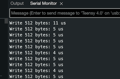
Fig. 7. Measured write time of 11 μs for the first 512-byte sector, followed by 5 μs per subsequent sector.
Python Log Viewer
The log viewer is implemented in Python to analyze the files retrieved from the SD card. It relies on three open-source libraries: struct for decoding the binary data, pandas for organizing the records, and plotly for plotting the flight data. Together, these libraries are integrated into flight_log_viewer.py, which calls parse_flight_log() to read the log file and plot_flight_data() to display the flight data.
if __name__ == "__main__":
    filename = "flight_log_001.bin"
    parameters, df_logs = parse_flight_log(filename)
    plot_flight_data(parameters, df_logs)
Parsing Flight Log
The parser starts by reading all bytes from the binary file and storing them in the data variable.
def parse_flight_log(filename):
    with open(filename, "rb") as file:
        data = file.read()
The parser then proceeds through the byte stream in a loop, extracting and validating the header of each record. It unpacks the two-byte sync field with the format string "<H" and compares it against the unique sync word 0xA55A. If the sync is valid, the log type is read from the following byte.
def parse_flight_log(filename):
    # ...
    while offset + 3 <= data_len
        # ...

        # ---- SYNC CHECK ----
        sync = struct.unpack_from("<H", data, offset)[0]
        if sync != SYNC:
            print("Desync at offset", offset)
            break

        log_type = data[offset + 2]

        # ...
Once the log type is identified, the parser unpacks the corresponding payload, either a ParametersLog or a FlightLog. The first record is always the parameters log, so its data is unpacked according to its format string, and the resulting values are mapped to the corresponding fields of the C++ structure. If parsing succeeds, its session_id is stored as a reference for validating the subsequent flight logs.
PARAMETERS_FIELDS = [
    "sync","type","session_id",
    # ...
    "vertical_velocity_kp","vertical_velocity_ki","vertical_velocity_kd"
]
PARAMETERS_FORMAT = "<HBI" + "f"*18
LOG_TYPE_PARAMETERS   = 1
# ...
def parse_flight_log(filename):
    # ...
    parameters = None
    session_id_from_parameters = None
    # ...
    while offset + 3 <= data_len
        # ...

        # ---------- PARAMETERS LOG----------
        if log_type == LOG_TYPE_PARAMETERS:
            params_raw = struct.unpack_from(PARAMETERS_FORMAT, data, offset)
            parameters = dict(zip(PARAMETERS_FIELDS, params_raw))
            session_id_from_parameters = parameters["session_id"]
        # ...
Similarly, each flight record is unpacked according to its format string and mapped to the corresponding fields of the C++ structure. Two additional checks are performed to ensure that each record belongs to the same flight session and that the timestamps remain in chronological order.
FLIGHT_FIELDS = [
    "sync","type","session_id","time_us",
    # ...
    "gyro_x","gyro_y","gyro_z",
    # ...
]
FLIGHT_FORMAT = "<HBII 4H " + "f"*27 + "5B"
LOG_TYPE_FLIGHT = 2
# ...
def parse_flight_log(filename):
    # ...
    last_time = None
    session_id_from_parameters = None
    logs = []
    # ...
    while offset + 3 <= data_len
        # ...
        # ---------- FLIGHT LOG ----------
        elif log_type == LOG_TYPE_FLIGHT:
            # ...
            flight_raw = struct.unpack_from(FLIGHT_FORMAT, data, offset)
            # ...
            flight_session_id = flight_raw[2]
            time_us = flight_raw[3]
            # ...
            # ---- SESSION CHECK ----
            if flight_session_id != session_id_from_parameters:
                print(
                    f"Session ID mismatch at {offset}: "
                    f"record = {flight_session_id}, "
                    f"expected = {session_id_from_parameters}"
                )
                break
            # ...
            # ---- MONOTONIC TIME CHECK ----
            if last_time is not None and time_us < last_time:
                print(
                    "Time reversal at", offset,
                    time_us * 1e-6, "<", last_time * 1e-6
                )
                break

            last_time = time_us
            logs.append(dict(zip(FLIGHT_FIELDS, flight_raw)))
            # ...
Plotting Flight Data
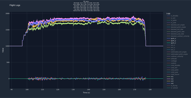
Fig. 8. Final log viewer displaying all flight data parsed from the binary file.
At this point, the parsed flight data is organized into a pandas DataFrame. Plotly then creates a trace for each field, configures the plot layout, and displays the flight data, as shown in Fig. 8.
def plot_flight_data(parameters, df_logs):
    # ...
    plot_logs = graph.Figure()

    plot_fields = [
        "rc_throttle","rc_roll","rc_pitch","rc_yaw",
        # ...
    ]

    for field in plot_fields:
        if field in df_logs.columns:
            figure_logs.add_trace(graph.Scatter(
                x=df_logs["time_s"],
                y=df_logs[field],
                name=field,
                # ...
            ))

    plot_logs.update_layout(
        title="Flight Logs",
        # ...
    )
    # ...
    plot_logs.show(config=config)
Plotting the timestamp differences and loop frequency is important for analyzing variations in the loop rate (Fig. 9). These plots help diagnose loop-rate blocking and lost records caused by insufficient buffer capacity.
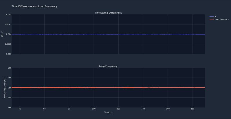
Fig. 9. Loop frequency maintained at the 250 Hz target without deviation.
Lesson
My journey through this flight data logger project has been a rewarding experience of experimenting and learning. This project helped me better understand the concepts behind more complex flight data loggers found in popular flight controllers, which often rely on more sophisticated log structures and parsing methods. Hopefully, this project can also give you a starting point for learning more about flight data logging.
Lastly, I want to mention that my implementation is good enough to capture and analyze raw flight data, but it is not yet optimized. There is still a lot of work to be done, such as reducing the amount of storage used on the microSD card, recovering from corrupted logs, and creating an optimized log format.
References
- Teensy 4.0, https://www.pjrc.com/store/teensy40.html
- IMXRT1060 Manual, Rev2, https://www.pjrc.com/teensy/IMXRT1060RM_rev3_annotations.pdf
- Betaflight, “Blackbox Logging Internals.” https://betaflight.com/docs/development/Blackbox-Internals
- Ardupilot, “Adding a new Log Message.” https://ardupilot.org/dev/docs/code-overview-adding-a-new-log-message.html
- Madflight, “Black Box Data Logging.” https://madflight.com/Black-Box/
- J. Hwang, “Ulog Flight logging System.” https://px4.io/px4-uorb-explained-part-4-ulog-flight-logging-system/
- PX4, “ULog File Format.” https://docs.px4.io/main/en/dev_log/ulog_file_format
- SD Association, “History of SDIO Standardization” https://www.sdcard.org/developers/sd-standard-overview/sdio-isdio/
- Majenko Technnologies, “Fast, Efficient Data Storage on an Arduino.” https://hackingmajenkoblog.wordpress.com/2016/03/25/fast-efficient-data-storage-on-an-arduino/
- J. Simon, et al, “Design and Implementation of SD Host Controller IP Core.” https://www.design-reuse.com/article/60302-design-and-implementation-of-sd-host-controller-ip-core/
- Yannik, “SD and SDIO.” https://yannik520.github.io/sdio.html
- Aimagin, “How to Use Data Logger.” https://support.aimagin.com/projects/support/wiki/How_to_Use_Data_Logger
- E. Mallon and P. Beddows, “Underwater Arduino Data Loggers.” https://thecavepearlproject.org/how-to-build-an-arduino-data-logger/
- Homemade multibody dynamics, “Datalogging on Arduino.” https://hmbd.wordpress.com/2017/03/18/datalogging-on-arduino-and-compatibles/